How to use the diagnostics function of Launch X431 PAD V
1. Intelligent Diagnosis Through simple Wi-Fi communication between the tablet and VCI, you can easily get the VIN (Vehicle Identification Number) information of the currently identified vehicle. Once the VIN is successfully identified, the system will retrieve it from the remote server and then guide you to vehicle information page without the necessity of step-by-step manual menu selection. The vehicle information page lists all historical diagnostic records of the vehicle, which lets the technician have a total command of the vehicle faults. In addition, a quick dial to local diagnosis and diagnostic function are also available on this page for reducing the roundabout time and increasing productivity
- Notes:
•Before using this function, please make sure the VCI is properly connected to the vehicle’s DLC. For detailed connection, see Chapter 5.1.3 “Vehicle Connection”. •A stable network connection is required for this function.
Follow the steps below to proceed. 1.Tap “Intelligent Diagnose” on the Job Menu to enter Fig. 1.
2.After pairing is complete, the handset starts reading the vehicle VIN. A.If the VIN can be found from the remote server database, a screen similar to the following figure displays:
•Tap “Diagnostic” to start a new diagnostic session. •Tap “Scan History” to view its historical repair record. If there are records available, it will be listed on the screen in sequence of date. If no records exist, the screen will show “No Record”.
•Tap “View record” to view the details of the current diagnostic report. •To perform other functions, tap “Quick access” to directly go to the function selection screen. Choose the desired one to start a new diagnostic session.
In this mode, you need to input the VIN manually or tap to scan it. 1)Tap to launch the VIN recognition module.
Place the VIN inside the viewfinder rectangle to scan it. The most recognizable location for this number is in the top left corner on the vehicle’s dashboard. Other locations include the driver’s door or post, and the firewall under the hood. •To switch the display orientation, tap . •To turn the flash on, tap How-to-use-the-diagnostics-function-of-x-431-pad-v-7 . •If you have scanned the VIN of the vehicle, tap to choose it from the record list. •In case the handset failed to detect it, tap to enter it manually. •Tap to switch the camera to barcode pattern recognition mode. • indicates the camera is in character pattern recognition mode (default mode). After scanning, the screen automatically displays the result.
2. Local Diagnosis Tap “Local Diagnose” to enter the vehicle selection page. 2 approaches are provided for you to access the vehicle diagnostic software. Choose any one of the following ways: 1.VINSCAN This function enables you to access it more quickly.
In this case, automatic scan (OBD VIN) and manual input (INPUT VIN) are available. Tap “VINScan”, the screen displays as follows:
A.Camera Scan: In this mode, the VCI device should be plugged into the vehicle’s DLC. Tap “Camera Scan”, a screen similar to the following appears:
Place the VIN inside the viewfinder rectangle to scan it. The most recognizable location for this number is in the top left corner on the vehicle’s dashboard. Other locations include the driver’s door or post, and the firewall under the hood.
•To switch the display orientation, tap . •To turn the flash on, tap . •If you have scanned the VIN of the vehicle, tap to choose it from the record list. •In case the handset failed to detect it, tap to enter it manually. •Tap to switch the camera to barcode pattern recognition mode. • indicates the camera is in character pattern recognition mode (default mode). Once the test vehicle is successfully identified, the tablet will jump to the function selection page directly. Tap the desired option to perform the corresponding function.
•To switch the display orientation, tap . •To turn the flash on, tap . •If you have scanned the VIN of the vehicle, tap to choose it from the record list. •In case the handset failed to detect it, tap to enter it manually. •Tap to switch the camera to barcode pattern recognition mode. •indicates the camera is in character pattern recognition mode (default mode).
B.INPUT VIN: In this mode, you need to input the VIN manually. In general, vehicle identification numbers are standardized – all contain 17 characters. VIN characters may be capital letters A through Z and numbers 1 through 0; however, the letters I, O and Q are never used in order to avoid mistakes of misreading. No signs or spaces are allowed in the VIN.
Tap “INPUT VIN” and a screen similar to Fig. 15 will appear:
Input the VIN, and tap “Confirm”, the system will automatically identify the vehicle model and directly navigate to the function selection page. 2.Manual Selection Tap a corresponding diagnostic software logo, and then follow the on- screen instruction to access the diagnostic software. Take Demo as an example to demonstrate how to diagnose a vehicle. 1). Select diagnostic software version: Tap the “DEMO” to go to Step 2. (*Note: If more than one version is available on this tablet, it will be listed on the screen.)
On-screen Buttons:
Vehicle Coverage: Tap to view the vehicle models that the current diagnostic software covers. What’s new: Tap to view the optimized items and enhancements. Introduction: Tap to check the software function list. Note: Tap to read some precautions on using the current diagnostic software. OK: Tap it to go to next step. 2). Select test item: Select the desired test item to proceed.
3. Health Report (Quick Test) This function varies from vehicle to vehicle. It enables you to quickly access all the electronic control units of the vehicle and generate a detailed report about vehicle health. Tap “Health Report”, the system starts scanning the ECUs. Once the scanning is complete, a screen similar to the following appears:
In Fig. 18, the tested system with fault code appears in red and the system with OK displays in white (normally).
- Note: Diagnostic Trouble Codes or Fault Codes can be used to identify which engine systems or components that are malfunctioning. Never replace a part based only on the DTC definition. Retrieving and using DTCs for troubleshooting vehicle operation is only one part of an overall diagnostic strategy. Follow testing procedures (in vehicle’s service manual), instructions and flowcharts to confirm the locations of the problem.
On-screen Buttons: : Tap to display the details of DTCs existing in the current system. Tap to hide it. Highlight certain DTC item, and tap to open the browser to retrieve it in Google engine.
Enter: Tap to select other test functions.
Report: Tap to save the diagnostic result as a report.
- Note: Diagnostic report is classified into three categories: Pre-Repair report, Post-Repair report and Diagnostic Scan. No matter which type you saved the report as, the report type will be appended as a tag on the upper right corner of the diagnostic report for easier identification.
Tap to select the report type from the option list and input the required information, and then tap “OK”.
- Note: To facilitate the comparison of the pre-repair and post-repair reports and get accurate test result, please make sure you saved the right type of the diagnostic report.
To save the report as a common diagnostic report, select “Diagnostic Scan”.
Enter the technician and customer name and then tap “OK” to confirm and navigate to the report details page.
- Note: For workshop information, tap “Change” to revise it. Alternatively you can also set it in “User Info” -> “Settings” -> “Print Information”.
Once you configured the information, it will be automatically generated every time you saved the diagnostic report. All vehicle and workshop information will be appended as tags on the diagnostic report.
To ignore the workshop information, tap “Skip” to go to the report details page. On the report details page, tap “Save” to save it. All diagnostic reports can be accessed from “User Info” -> “My Reports” -> “Health Report”. Help: Tap to view the help information of the selected DTC item. Compare Results: Tap to select the pre-repair report to compare. By comparison of the pre- and post- repair reports, you can easily identify which DTCs are cleared and which remain unfixed.
- Note: Before performing this function, please make sure that:
•You have saved a pre-repair report of the currently tested vehicle, and •You have already made some repairs and service and cleared the DTCs after the pre-repair reported is generated. Otherwise, no differences exist between the pre- and post- repair reports.
Clear DTC: Tap to clear the existing diagnostic trouble codes.
- Note: Clearing DTCs does not fix the problem(s) that caused the code(s) to be set. If proper repairs to correct the problem that caused the code(s) to be set are not made, the code(s) will appear again and the check engine light will illuminate as soon as the problem that cause the DTC to set manifests itself.
System Scan This option allows you to quickly scan which systems are installed on the vehicle. In Fig. 17, tap “System Scan”, the system starts scanning the systems. Once the scanning is complete, the screen will display the result.
Tap the desired system to advance to the test function selection page. For detailed operations on test function, please refer to Chapter 5.3.2.3.
System Selection This option allows you manually select the test system and function step by step. In Fig. 17, tap “System Selection”, the screen displays as follows:
Swipe the screen from the bottom to view the vehicle system on the next page. Tap the desired system (take “ECM” for example) to jump to the test function page.
- Note: Different vehicle has different diagnostic menus.
A.Version Information This function is used to read the version information of system mode, vehicle VIN, software and ECU. In Fig. 27, tap “Version Information”, the screen displays as follows:
Tap “OK” to confirm and exit. B.Read Fault Code This function displays the detailed information of DTC records retrieved from the vehicle’s control system. In Fig. 27, tap “Read Fault Code”, the screen will display the diagnostic result.
- Note: Retrieving and using DTCs for troubleshooting vehicle operation is only one part of an overall diagnostic strategy. Never replace a part based only on the DTC definition. Each DTC has a set of testing procedures, instructions and flow charts that must be followed to confirm the location of the problem. This information can be found in the vehicle’s service manual.
On-screen Buttons: Freeze Frame: When an emission-related fault occurs, certain vehicle conditions are recorded by the on-board computer. This information is referred to as freeze frame data. Freeze frame data includes a snapshot of critical parameter values at the time the DTC is set. Help: Tap to view the help information. Code Search: Tap it to search for more information about the current DTC online. Report: To save the current data in text format. All diagnostic reports can be accessed from “User Info” -> “My Reports” -> “Diagnostic Report”. C.Clear Fault Code After reading the retrieved codes from the vehicle and certain repairs have been carried out, you can use this function to erase the codes from the vehicle. Before performing this function, please be sure the vehicle’s ignition key is in the ON position with the engine off. Clearing DTCs does not fix the problem(s) that caused the code(s) to be set. If proper repairs to correct the problem that caused the code(s) to be set are not made, the code(s) will appear again and the check engine light will illuminate as soon as the problem that cause the DTC to set manifests itself. In Fig. 5-25, tap “Clear Fault Code”, a confirmation dialog box pops up on the screen. Tap “Yes” and the system will automatically delete the currently existing trouble code.
- Note: After clearing, you should retrieve trouble codes once more or turn ignition on and retrieve codes again. If there are still some trouble codes in the system, please troubleshoot the code using a factory diagnosis guide, then clear the code and recheck.
D.Read Data Stream This option lets you view and capture (record) real-time Live Data. This data including current operating status for parameters and/or sensor information can provide insight on overall vehicle performance. It can also be used to guide vehicle repair.
- Note: If you must drive the vehicle in order to perform a troubleshooting procedure, always have a second person help you. Trying to drive and operate the diagnostic tool at the same time is dangerous, and could cause a serious traffic accident.
In Fig. 27, tap “Read Data Stream”, the system will display data stream items.
On-screen Buttons: Select All: Tap it to select all items of the current page. To select certain data stream item, just check the box before the item name. Unselect: Tap it to deselect all data stream items. OK: Tap it to confirm and jump to the next step. After selecting the desired items, tap “OK” to enter the data stream reading page.
- Notes:
1.If the value of the data stream item is out of the range of the standard (reference) value, the whole line will display in red. If it complies with the reference value, it displays in blue (normal mode). 2.The indicator 1/X shown on the bottom of the screen stands for the current page/total page number. Swipe the screen from the right/left to advance/return to the next/previous page.
•Value – this is the default mode which displays the parameters in texts and shows in list format. •Graph – displays the parameters in waveform graphs. •Combine – this option is mostly used in graph merge status for data comparison. In this case, different items are marked in different colors. On-screen Buttons: : Tap it to view the waveform graph of the current data stream item.
- Note: The real time (Live Data) vehicle operating information (values/status) that the on-board computer supplies to the tool for each sensor, actuator, switch, etc. is called Parameter Identification Data (PID).
Graph: Tap it to view the waveform.
•Combine: This option is mostly used in graph merge status for data comparison.
•Value: Tap to display the parameters in texts. •Customize: Tap , a pull-down list of the data stream items appears on the screen. Select (Maximum 8 data stream items can be selected)/deselect the desired items and then screen will display/remove the waveforms corresponding to these items immediately.
Select Sample DS: Tap it to select the sample DS file, the values you customized and saved in process of DS sampling will be imported into the “Standard Range”(See below) column for your comparison.
- Note: Before executing this function, you have to sample the values of data stream items and save it as an sample DS file.
Report: To save the current data as a diagnostic report. All diagnostic reports can be accessed from “User Info” -> “My Reports” -> “Health Report”. Record: Tap to start recording diagnostic data. Recorded live data can serve as valuable information to help you in troubleshooting of vehicle problems. All diagnostic records can be replayed from “User Info” -> “My Reports” -> “Recorded Data”.
- Note: The saved file follows the naming rule: It begins with vehicle type, and then the product S/N and ends with record starting time (To differentiate between files, please configure the accurate system time).
Help: Tap to view the help information. Sample DS: This item enables you to customize the standard range of live data stream items and save it as DS sample file. Each time you run the data stream items, you can call out the corresponding sample data to overwrite the current standard range. Tap it to start recording the sample data (*Only data stream items with measurement units will be recorded), and the screen displays as below:
Once recording is complete, tap to stop it and navigate to the data revision screen.
Tap the Min./Max. value to change it. After modifying all desired items, tap “Save” to save it as a sample DS file. All DS files are stored under the “Data Stream Sample” file in “User Info.”. E.Actuation Test This option is used to access vehicle-specific subsystem and component tests. Available test vary by vehicle manufacturer, year, and model. During the actuation test, the tablet outputs commands to the ECU in order to drive the actuators, and then determines the integrity of the system or parts by reading the ECU data, or by monitoring the operation of the actuators, such as switching a injector between two operating states. In Fig. 27, tap “Actuation Test”, the system will display as follows:
Simply follow the on-screen instructions and make appropriate selections to complete the test. Each time when an operation is successfully executed, “Completed” displays.
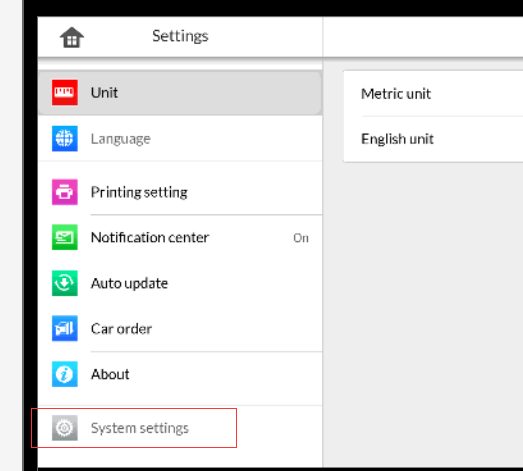
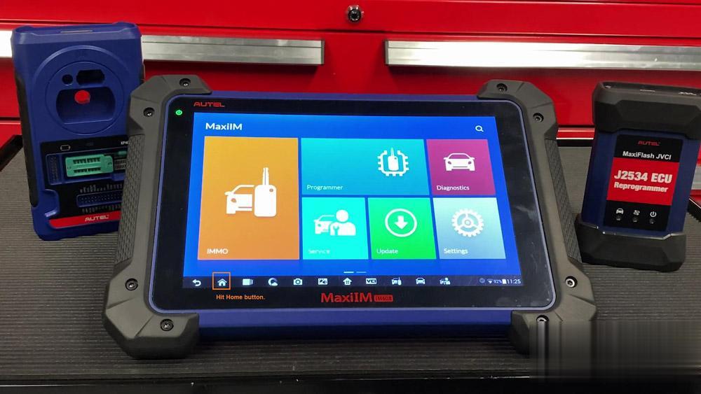 Then , select “System Settings”.
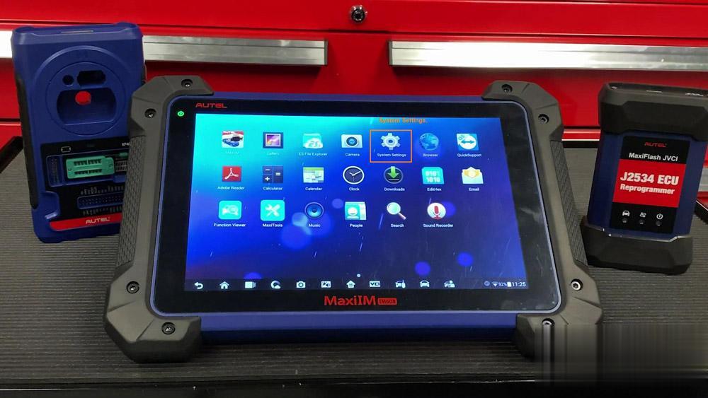

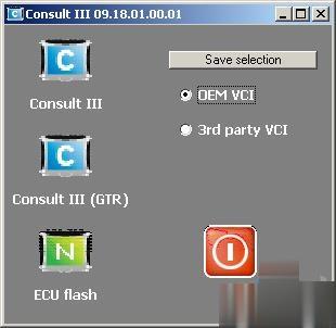
 Confirm the selection with the Confirm button :
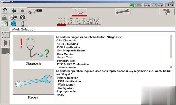
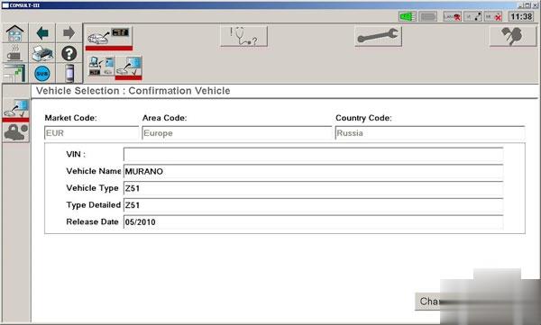 Choose Diagnosis :
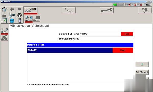
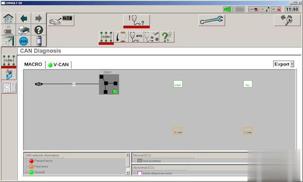
 Select the type of Can- bus according to the configuration, in this case, the very first, and click the Next button :
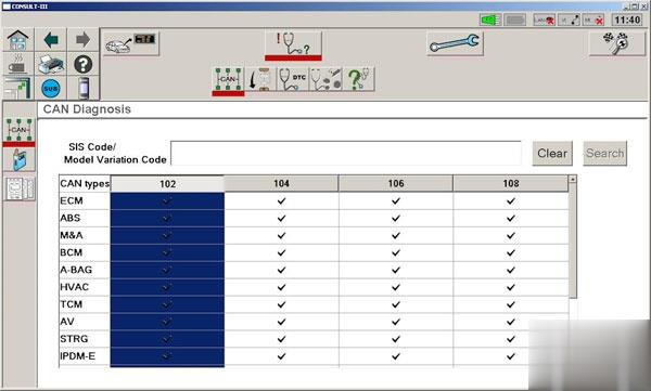 Click on the tablet (top left):
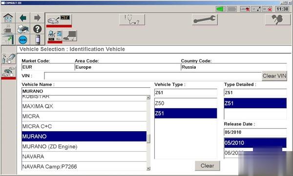
 Choose System Diagnosis :
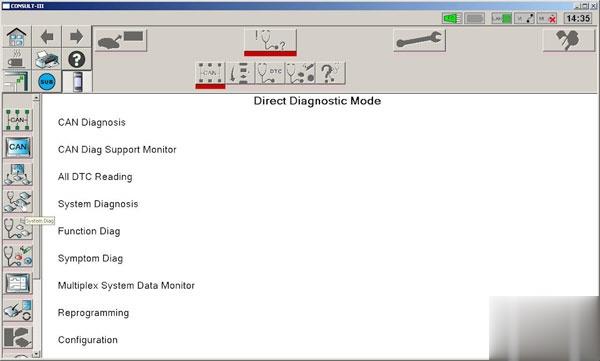 Click on Transmission and OK :
 Moving towards Work Support :
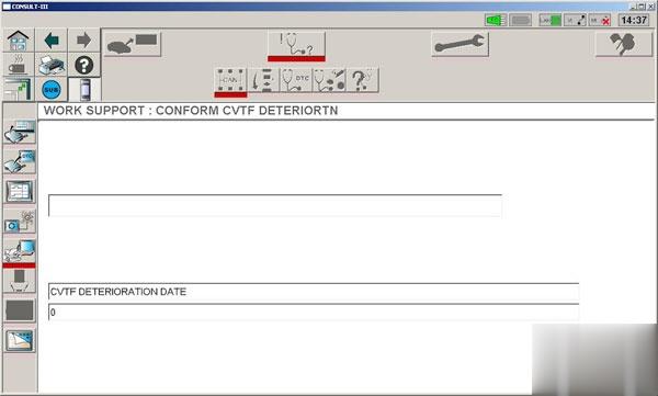
 Click on Conform CVTF Deteriortn and Next :
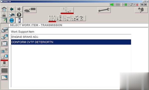 At the moment, the fluid counter shows 7897
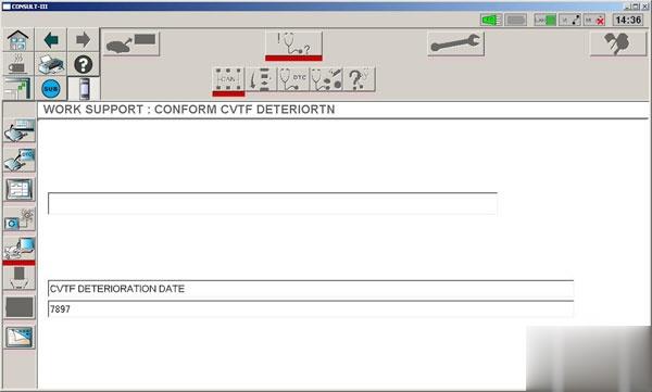 Click the Clear button and once again agree:
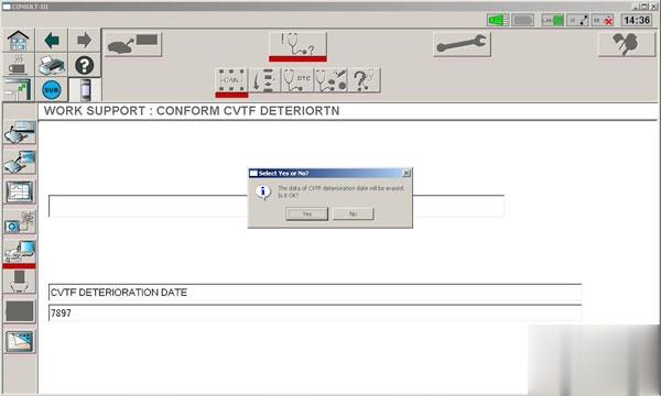 Counter reset:
 Done.
Done.